Purpose
Conventional engraving for signage can be performed by any one of four basic methods – all of which result in the removal of material from the surface of a workpiece. This BLOG entry outlines each of the three engraving methods, common materials and the technology available for increasing efficiency and quality of the end product.
Four Types of Equipment:
The pantograph is a manually operated machine that removes material using a rotating tool or diamond scribe. The tool is connected by levers to a stylus that is moved manually by the operator. The operator uses the stylus to trace a template of each letter. Because the tool follows the motion of the stylus, each letter must be precisely positioned to reflect the actual layout of the work. While pantographs are still used widely to engrave small plates at shopping mall stores like Things Remembered, they are generally considered an inefficient and outdated technology for industrial or 3D engraving. This is because the process requires and operator who is tied to the machine for the duration of the process. Not only is this costly in terms of labor, but the quality of the end product is dependant upon the skill and experience of an individual operator and may vary from shift to shift or part to part. Skilled pantograph operators are truly craftsmen of a dying art form. As a result, it is becoming increasingly hard for manufacturers to find qualified operators – and what they may save on the cost of equipment is usually offset by the cost of labor. Additionally, since the process is extremely taxing from a physical and ergonomic standpoint, employers are vulnerable to the added costs of workman’s compensation or disability.
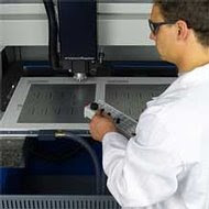
So, most engraving today is done with CNC (Computer Numeric Control) engravers and routers. The CNC engraver uses a rotating tool to remove material. The engraving is designed on computer software, converted to numeric commands for each axis of motion. These commands are sent to the machine and the spindle that spins the tool is moved by stepper motors or servo motors. While quality and repeatability are clear advantages for CNC routers, the process can also be performed by an unattended machine which lowers the cost of labor. Additionally, some CNC routers are multi-tasking industrial workhorses capable of engraving, milling, cutting, tapping and routing at a single work cell – throughout a 24/7/365 production schedule. This provides manufacturers with the flexibility to produce more complex engraved parts, the efficiency to increase throughput and the agility to take on new multi-phase projects.
Laser engravers are a type of CNC machine that use a focused laser beam, instead of a rotating tool, to remove material. While lasers rival CNC routers in terms of speed and quality, the type of cut that they produce generally doesn’t appear “authentic”. That’s because lasers don’t penetrate the workpiece as deep as rotary engraving and it lacks the look and feel of traditional engraving. Another drawback of laser engravers is that they often require special types of engraving material – so the substrates available as “blanks” are limited in color and texture and are more costly than those available for rotary CNC engraving.
Finally, there is stamping. With this process, a die is made for use with the stamping machine. Each die costs in the range of $2,000 to $3,000. For high volume production, say 20,000 parts, stamping is a logical choice because the stamping machine can produce a couple parts per second. But, for low volumes the cost of the dies cannot be justified. Another down side to this process is that the edge quality is far inferior to parts made on a CNC router. This is because the stamping machine removes material from the workpiece by pushing the die down through the material like a cookie cutter. The force created at the location of the cut bends and shears the substrate. With malleable materials like metal this can mean bending at the edge and with other more brittle substrates, chipped edges can result. Finally, unlike the multi-purpose CNC routers mentioned above, the stamping machines are limited to stamping. So if the end product requires a counter sunk hole or tapping, this would require another piece of equipment and a secondary operation – both at additional cost to the manufacturer.
Types of Material:
Engravers use a variety of mediums to produce signs and nameplates. While some engraving is done in more exotic materials like Dupont Corian (a synthetic resin stone), most engravers use brass, aluminum, and layered plastics.
Metals
Solid brass and aluminum plates come in a variety of colored lacquers. Typically, these plates are very thin (about .025”) enabling the engraver to cut and size them for mounting on a plaque board or placing in a frame. Engraving in brass is usually done by removing the lacquered coating with a rotating tool in order to expose the shiny metal surface underneath. This process is called burnishing. Unlike deep engraving, which removes a considerable amount of metal, burnishing barely penetrates the surface of the material. Deep engraving (or milling) of metal is used primarily to make industrial molds and name plates.
Wood
Wood and is other common material used by engravers. Wood is a good material for rotary engraving, though it typically involves more processing time. That’s because after the image or text is cut, the engraved recesses often need to be stained or filled with paint to enhance legibility.
Plastics
Like brass and aluminum, engraving plastic is produced in thin sheets (typically 1/16” and 1/32” thick) which can be cut and trimmed to size, then mounted on a plaque board or placed in a decorative frame. The material is layered in a two-color sandwich usually composed of Acrylic or ABS. A rotary tool is used to remove the colored surface material to a depth of .003”-.015”. This exposes the core that contains the second color. Of all the materials available to an engraver, these co-extruded and micro-surfaced resins offer the greatest selection of color, texture, and finish. While some tend think of plastics as cheap looking plastic nameplates, new high tech, co-extruded and micro-surfaced resins can produce quality end products. Unlike lacquered metal, this new generation of engraving material is scratch resistant, it does not oxidize, some of it is durable enough to mount outdoors, and it comes in variety of finishes that effectively simulate stone and metal.
Features That Provide The Competitive Edge:
High-Speed SpindleMost ID product and nameplate engraving is done with small engraving bits and endmills. These small tools must be run at high speeds. High-speed CNC engraving machines featuring 60,000 RPM spindles effectively evacuate chips from the cutting channel resulting in smooth surfaces and burr-free edges. This eliminates the need for the secondary de-burring operation, as well as the costs associated with it. The 60,000 RPM spindle is designed specifically for engraving and milling with small tools. Unlike conventional CNC spindles designed to run large tools, high frequency (high speed) spindles have smaller motors and produce less force. This helps to maximize tool life by minimizing the force that leads to tool breakage. Conventional CNC machines would have to be run at very low speeds in order to prevent the force of the spindle from breaking these small tools. As a result, cycle times are long and surface finish is inadequate for most engraving applications.
Probing
Probing saves time during job setup and ensures accuracy and repeatability. Probes available as an integrated component on some rotary CNC engravers can recognize irregular work-piece topography and compensates for it dynamically. They do this by taking measurements along the surface of a blank and feeding that data into the machining controller. The controller automatically adjusts for uneven surfaces or work piece position. Through this process, job setup times are reduced and piece/part rejection is minimized. With a 3D extension, the probe locates parts and material irregularities in the X, Y, and Z co-ordinates, finds centers of holes and bosses, pre-measures blanks before the machining starts, compensates for material variations, feeds data into ISO 9000 information chain for quality control, and even allows for the reverse engineering of many parts.
Oil-Free Coolant
While Probing can save valuable time at the front end of production, during set up, oil-free coolants like ethanol can save time at the back end. That’s because unlike oil leaves a residue on the completed product, ethanol simply evaporates. So, the secondary de-greasing operation can be eliminated – thereby reducing the cost of labor, the cost of consumables required for cleaning and, most importantly, minimizing total production time. Ethanol is a form of alcohol that results naturally through the sugar fermentation process and is environmentally friendly. It also happens to be an ideal coolant for high-speed, micro machining because a thinner-than-water viscosity allows the ethanol to quickly cover and cool more surface area on fast-moving micro tooling. The low evaporation point of ethanol makes it an efficient cooling solution and also eliminates the need for disposal and recycling, as well as their associated costs.
Note: Ethanol coolant should only be used for machining of non-ferrous materials and manufacturers can switch over to oil coolant when machining or engraving steel-based materials.
Integrated Workholding
Workholding for nameplate applications, like production runs of Metalphoto, can be problematic. Thin substrates are difficult to hold. This is particularly true if the manufacturer is using a conventional CNC to engrave or cut small parts with limited surface area, because the force of the spindle can literally “fling” the part across the machine bed once it is completely cut out. Many manufacturers actually resort to spray glue as a method of workholding. Not only is this messy, it can also lead to bending when the finished part is removed from the machine bed, it sometimes doesn’t hold the part when it is completely cut out … and it results in a time consuming and costly secondary application to remove the glue form the completed parts.
Therefore, high-speed CNC engravers and routers are the logical choice for ID Product and Nameplate manufacturers. As mentioned above, these machines are designed exclusively for running small tools and inherently have smaller motors that produce less force. This low force enables innovative workholding technology. For example, some CNC manufacturers have developed vacuum tables that are integrated with the machine bed. So, thin stock, which could be secured only with great difficulties before, is now secured literally within seconds. Plastic foils as thin as 0.001”, to 0.250” large aluminum sheets are secured quickly and held in place even when the parts are “cookie-cut” completely through the material. A vacuum pump provides vacuum power for the system to work. A vacuum table features airflow-optimized vacuum ports, with recessed vacuum chambers, to provide superior vacuum distribution. A low cost gas-permeable substrate serves as a sacrificial vacuum diffuser, allowing the cutter to machine through the workpiece, without cutting into the table.
Automatic Tool Management
ID Product and Nameplate manufacturers considering various CNC machines for milling and engraving, need to consider their current processes and what their ideal process might be. In other words, they may currently be running only one or two shifts, but in a perfect world, an unattended overnight shift could be the secret to increased profitability. Even if a “lights-out” shift just isn’t in the cards, a day shift where the CNC machine can run unattended allows the operator to tend to other business – thereby providing the manufacturer with more productivity from a single employee. So, choosing a CNC with the right kind of tool management is crucial.
In the world of machining with large tools, monitoring spindle load can be used as a means of detecting breakage. If there is a fluctuation or drop-off in the current, then the operator knows that the tool might be broken. Unfortunately, the benefits of this “Tool Detection” process are limited because it is used only as a means of checking tools and reporting possible breakage without systematically replacing the broken tool. So, the best that a manufacturer can hope for is that the machine will shut off and prevent additional damage to costly blanks. Still, production time is lost — and if the tool breakage occurs early in a “lights-out” overnight shift, it can significantly impact schedules and revenue. Furthermore, this method doesn’t work when using micro tooling because the load involved is sometimes so small that the fluctuation in power usage doesn’t even register.
CNCs with an Automatic Tool Management System are a better solution. The Automatic Tool Management System is made up of three separate components working in synergistically — the tool checker, the tool changer, and the software. The tool checker is a mechanical sensor that measures tool length and detects the broken tool. The tool changer is a rack or tray that has space for spare tools and sockets where the machine places broken tools before picking up a replacement. Operators can stock the rack with spare tools, thereby having a ready supply should tools break during “lights out” operation. The software is a macro program that can be set up to run a tool check after executing a number of lines of code. For example, a tool check macro can initiate a check after every 500 lines of code by employing an “if/then” statement such as, “Measure this tool; if the length is shorter than the parameter (listed in the software’s tool database), then change the tool.”
Wrapping It Up:
ID Product, Nameplate and Signage Manufactures who specialize in low production runs can gain efficiency, flexibility and an overall reduction in cost by using rotary-type CNC engravers and routers. Since most of these manufacturers use small tools, it is imperative that they select a CNC machine designed specifically for use with small tools. High-speed spindles are best suited for small tools and produce burr-free parts with superior surface and edge finishes. The low force of these spindles maximizes tool life and enables innovative workholding that speeds setup time, improves efficiency and makes secondary operations like de-greasing obsolete. Probing also makes setup more efficient and ensures accuracy and repeatability. Automatic Tool Management provides a reduction in cost by enabling unattended or lights-out production. CNC machines that deliver all of these features, working synergistically, provide manufacturers of ID Products, Nameplates and signage with a means to revolutionize their business.
Monday, April 13, 2009
Sunday, March 15, 2009
Variations on CNC Chassis Design
Purpose
This BLOG entry focuses on the varying methods of chassis design and fabrication for CNC machines. Further, it is intended to help with comparative evaluations within the microtooling CNC niche. This will be done, first, by explaining why machines designed for microtooling should not be compared to other conventional CNC machines designed to run large tools, and second, by providing information on each of the primary methods of chassis fabrication used in the manufacture of microtooling CNC machines.
The tale of the tape
With such a wide range of CNC machines on the market and an even larger number of applications for those machines, it’s logical that there’s a relative number of methods for chassis construction. The type of construction employed in the manufacture of a particular machine should be the direct result of extensive engineering and design — taking into account the physics involved in the applications the machine will be called upon to perform. So, when comparing CNC machines, it’s not always an apples-to-apples scenario. Just like you’d never see George Foreman vs. Oscar de la Hoya on the “Tale of the Tape”, a CNC machine intended to muscle through dense substrates with durable large tools should never be compared to machines intended for high-speed, micro-tooling. Nonetheless, machine comparison can be problematic when certain manufacturers try to be everything to everyone. For example, some makers of large-tool CNC machines tout the added capability of being able to run small microtools ... and they can. But, if you manufacture mostly small parts, this paper should prevent you from paying for both weight and bulk that you simply don’t need.
Let there be light
Small tools > Small Spindles > Less Force > Lighter Construction > Agility & Flexibility
With a trend towards miniaturization in many types of manufacturing, mills and drills with a diameter of 0.250” or less are the norm rather than the exception. To achieve superior surface finishes and avoid tool breakage, small tools require low-force and therefore high-speed that can only be delivered by spindles specifically designed for them. Conventional CNC machines, with hulking, high-horsepower spindles, simply cannot run small tools without breaking them or sacrificing both the cycle-time and the surface finish of the end product. That’s because RPM and feed rates must be slowed down to a snail’s pace in order to reduce the force on these fragile, small tools — and this results in burring and slow production times. So, as mentioned above, large-tool CNC machines can run microtools, but at what cost?
The smaller spindle designs for microtooling inherently produce less force and therefore allow for a “light” chassis construction that ultimately provides manufacturers with added agility and nimbleness. In particular, consider weight alone. Conventional CNC machines frequently weigh in at a whopping 25,000 lbs. while microtooling CNC machines can be as light as 1,500 lbs. which provides manufacturers with increased flexibility to adjust manufacturing cells to fit their changing needs.
Microtooling CNC machines — apples-to-apples?
Even in a comparative evaluation where large-tool CNC machines have been ruled out and the focus is on several different microtooling CNC machines, there are number of different chassis construction or fabrication methods to compare.
Welded Steel Plates: The least costly process is, in fact, the least desirable. Steel plates that are joined together by welding are susceptible to the effects of vibration. The welding process requires superheating of both solder and sheet metal in order to join plates together to form the chassis of the CNC machine. Within each cooled and hardened welded joint there exists significant tension that naturally is looking to escape. Vibration produced by the machine’s motor provides a means for that escape. When the tension is released due to this vibration, the chassis becomes deformed — perhaps not enough to be noticed by the human eye, but enough to sacrifice accuracy and repeatability.
Cast Steel: A more expensive process, aged casts exhibit excellent long-term stability. Through the reduction or even elimination of joints in the chassis of a CNC machine, it is inherently less likely to have its structural integrity compromised by vibration. However, casting is difficult to do on a large scale and this forces CNC makers to consider two options. Either reduce the size of the chassis (including bed size and work envelope) or join two or more casts together. Smaller bed sizes are logical for machines designed for one-up production or small batches, but not for true batch-machining. Joined casts, like welded steel plate construction, once again, provides a window of opportunity for vibration and deformation.
Polymer Concrete: Everyone knows that if you flick your finger against steel you can hear a reverberation, but if you try the same thing with concrete what you hear is a muffled thud and perhaps your own screams of pain. That’s because concrete absorbs vibration. So, by virtue of superior vibration dampening qualities, aged polymer concrete reigns supreme in the design and construction of a CNC machine chassis. Plus, this process can be used in concert with the other fabrication methods to yield vibration dampening and stability that they would not have on their own.
Wrapping it up
For manufacturers specializing in the production of small parts, a microtooling CNC machine featuring a concrete-polymer chassis, or one that combines concrete polymer with steel, provides both the vibration dampening qualities and long-term durability required to support continuous production and accuracy. At the same time, the CNC manufacturer can leverage the fact that the low-force, produced by high-speed spindles, allows for a lighter chassis construction. The resulting light-weight, concrete-polymer design provides the manufacturer with the flexibility to quickly adapt to changing needs by moving the machine to fit into various manufacturing cells. So, the manufacturer thereby exhibits an agility that gives them the competitive edge, improves time-to-market and significantly impacts their bottom line.
Sunday, February 1, 2009
Batch Machining with Micro-Tooling
This blog entry focuses on batch machining as it applies specifically to high-speed machining with micro-tooling. Topics covered include definitions, challenges, available technology and solutions. The paper’s purpose is to prove the direct correlation that batch machining (as an alternative to one-up production) has with a manufacturer’s profitability. Further, the ability to effectively implement batch machining relies on the presence of CNC machining systems featuring larger beds that facilitate “lights-out” production.
Defining batch machining, micro-tooling, and high-speed machining
Batch machining is defined as manufacturing a minimum of two parts on the machining table at any given time. This paper uses the terms “batch machining” and “batch processing” interchangeably. There is no limit to the number of parts that define a batch, but ideally the manufacturer achieves efficiencies by maximizing the space available on the machine bed and producing as many parts in one run as possible.
Micro-tooling involves mills and drills with a diameter of 0.250” or less. Higher RPM rates are required to run these small-diameter tools in an efficient and economical manner. The use of high-speed micro CNC machining systems that utilize high-frequency spindles with speed ranges from 6,000 to 60,000 RPM results in feed rates that produce significantly faster manufacturing times in intricate work-pieces, as well as superior edges and surface finishes.
High-speed machining has no set definition or absolute parameters, but one workable definition is machining with spindle speeds of 25,000 RPM or more.
The challenges of batch machining
When companies produce a batch of parts, they usually have an operator in front of the machine for an entire shift, producing work-pieces one at a time. The operator takes raw stock, puts it on the machine bed, machines the part and then removes it — repeating the entire process for eight hours. Therefore, the operator is dedicated or “tied” to a single machine. This procedure is known as “one-up” production.
Based on an 8-hour day, labor costs about $0.40 a minute and a machine costs about $0.20 a minute to operate. Therefore, if you tie an operator to the machine with one-up production, your total cost will be $0.60 a minute. If you were to run two shifts, the machine would cost only $0.10 a minute, while the labor cost remains the same at $0.40 a minute. Although it’s a savings, it falls short of maximizing the impact on a manufacturer’s bottom line … and more can actually be saved. By empowering the machine do the work without operator intervention during the second shift, the reduction in the labor cost brings the machine cost as low as $0.05 a minute.
Meeting the challenge
Batch machining on large beds reduces operator intervention since it accommodates sizable “blanks” and a full batch can have a cycle time that coincides with the length of an operator’s shift. That way, the operator can place a batch on the machine in the morning and attend to other duties during the day. The automated machine works all day producing the needed pieces. Near the end of the shift, the operator then removes the completed batch, sweeps down the machine, and sets up another batch to run unattended all night.
When the operator returns to work the next morning, he removes the batch that the machine produced overnight and starts up another one. This gets two shifts’ worth of work out of one operator. This is the principle of “lights out” production — so named because the machine is left running overnight when everyone has gone home. Bear in mind that the above example reflects the “ideal”, since it keeps the machine operating unattended for most of the workday and at night. This may not fit your exact application but, the closer you can get to that ideal, the more efficient and cost-effective your operation will become.
Note: Achieving the highest degree of efficiency or the “ideal”, requires increasing the machine’s role in the process while decreasing the need for operator supervision. So, manufacturers striving to reach this ideal must employ the right machines and also identify alternative labor functions to fill the void left by the operator’s diminished role in production.
The right tools for the job
Thanks to today’s technology there are many tools available for facilitating batch machining. Often, these tools are most effective when used in conjunction with one another. For the purpose of this paper these batch-machine tools have been divided into the categories “limited” and “optimal.”
Limited Tools
The following tools are useful but cannot fully support batch machining and are therefore defined as “limited”.
♦ Pallet changers. Economy-minded manufacturers try to increase efficiency by augmenting machining centers with the addition of a pallet changer. Pallet Changers allow the operator to exchange freshly made parts with a new blank — facilitating continuous machine operation and cutting down on machine idle time. Pallet changers usually run in the range of $10,000-20,000. Unfortunately, automatic pallets usually involve tying the operator to the machine making this accessory an inefficient solution that yields no significant savings. In the end, a company trying to save money has, in fact, just spent money on a pallet changer to make the operator’s job easier without further automating their process, facilitating “lights-out” production or significantly impacting their bottom-line.
♦ Robots. Robots demand an investment in both time and money. On average, a machining center costs about $80,000. The addition of a robot to the machining process requires another $30,000-40,000 — making the machine-robot combination a $100,000+ investment.
Robots replace workers, which certainly cuts labor costs but rather than simply programming them, they must be taught their tasks. So conducting batch-processing operations using robots requires significant set-up and preparation time. Additionally, robots usually don’t fit in the machine envelope due to their size and shape. Finally, robots need to be presented with the parts to be machined — often placing the burden on the manufacturer to develop a custom magazine design to ensure a continuous feed of parts to the robot.
Optimal Tools
These tools are far more suitable for batch-machining operations and are therefore defined as “optimal”. They are listed in descending order based on significance.
♦ CNC machine with large bed. In short, a large bed size accommodates a big enough sheet of stock to let the machine work all day long to yielding a significant amount of parts. Machines can be purchased with large bed sizes as an integrated feature as opposed to a more costly accessory. Large bed sizes also allow machining of larger parts and the ability to handle unexpected emergency machining tasks without disrupting regular workflow.
♦ Quick-Pallets™. These low-cost manual pallet changers are light and easily handled. Pallets enable a manufacturer to completely change their workholding setup in a few seconds. Pallets are mounted securely onto the machining bed via vacuum and keyed to a fixed position. This setup allows smooth batch machining operations with a rapid turnover. When the batch is completed, changing a pallet involves removing the old pallet, sweeping down the surface, and installing a new pallet, a process that takes seconds.
Light-weight pallets are available for different workholding solutions, including pneumatic short stroke clamps, vacuum plates, and blank panels for custom workholding solutions. Pallets are easily lifted by hand and provide a cost-effective solution to an old problem.
♦ Pick & Place Systems. For parts that need to be machined either along their circumference or on their face, machines can be fitted with a gripper, creating a “pick and place” system. Grippers can pick up a part from a pallet and secure it in a 4th (and 5th) axis in such a way that it can be machined from any and all sides.
Conclusion
While the cost of labor is something that the manufacturer cannot control, companies can still achieve substantial savings through batch machining that gets twice the work out of an operator with no increase in labor cost. This method can be expanded into “lights-out” production (one shift of unattended machining) to further reduce machine costs. Any form of batch machining is superior to one-up production and represents a “set it and forget it” method to achieve cost-effective, efficiency with machines that were designed to be automated in the first place.
A machine center featuring a large machine bed, Quick-Pallets and possibly a pick and place system, offers a complete solution for batch machining that will directly and positively impact a manufacturer’s bottom line.
Thursday, January 29, 2009
Variations on CNC Chassis Design
Purpose
This blog entry focuses on the varying methods of chassis design and fabrication for CNC machines. Further, it is intended to help with comparative evaluations within the microtooling CNC niche. This will be done, first, by explaining why machines designed for microtooling should not be compared to other conventional CNC machines designed to run large tools, and second, by providing information on each of the primary methods of chassis fabrication used in the manufacture of microtooling CNC machines.
The tale of the tape
With such a wide range of CNC machines on the market and an even larger number of applications for those machines, it’s logical that there’s a relative number of methods for chassis construction. The type of construction employed in the manufacture of a particular machine should be the direct result of extensive engineering and design — taking into account the physics involved in the applications the machine will be called upon to perform. So, when comparing CNC machines, it’s not always an apples-to-apples scenario. Just like you’d never see George Foreman vs. Oscar de la Hoya on the “Tale of the Tape”, a CNC machine intended to muscle through dense substrates with durable large tools should never be compared to machines intended for high-speed, micro-tooling. Nonetheless, machine comparison can be problematic when certain manufacturers try to be everything to everyone. For example, some makers of large-tool CNC machines tout the added capability of being able to run small microtools ... and they can. But, if you manufacture mostly small parts, this paper should prevent you from paying for both weight and bulk that you simply don’t need.
Let there be light
Small tools > Small Spindles > Less Force > Lighter Construction > Agility & Flexibility
With a trend towards miniaturization in many types of manufacturing, mills and drills with a diameter of 0.250” or less are the norm rather than the exception. To achieve superior surface finishes and avoid tool breakage, small tools require low-force and therefore high-speed that can only be delivered by spindles specifically designed for them. Conventional CNC machines, with hulking, high-horsepower spindles, simply cannot run small tools without breaking them or sacrificing both the cycle-time and the surface finish of the end product. That’s because RPM and feed rates must be slowed down to a snail’s pace in order to reduce the force on these fragile, small tools — and this results in burring and slow production times. So, as mentioned above, large-tool CNC machines can run microtools, but at what cost?
The smaller spindle designs for microtooling inherently produce less force and therefore allow for a “light” chassis construction that ultimately provides manufacturers with added agility and nimbleness. In particular, consider weight alone. Conventional CNC machines frequently weigh in at a whopping 25,000 lbs. while microtooling CNC machines can be as light as 1,500 lbs. which provides manufacturers with increased flexibility to adjust manufacturing cells to fit their changing needs.
Microtooling CNC machines — apples-to-apples?
Even in a comparative evaluation where large-tool CNC machines have been ruled out and the focus is on several different microtooling CNC machines, there are number of different chassis construction or fabrication methods to compare.
Welded Steel Plates: The least costly process is, in fact, the least desirable. Steel plates that are joined together by welding are susceptible to the effects of vibration. The welding process requires superheating of both solder and sheet metal in order to join plates together to form the chassis of the CNC machine. Within each cooled and hardened welded joint there exists significant tension that naturally is looking to escape. Vibration produced by the machine’s motor provides a means for that escape. When the tension is released due to this vibration, the chassis becomes deformed — perhaps not enough to be noticed by the human eye, but enough to sacrifice accuracy and repeatability.
Cast Steel: A more expensive process, aged casts exhibit excellent long-term stability. Through the reduction or even elimination of joints in the chassis of a CNC machine, it is inherently less likely to have its structural integrity compromised by vibration. However, casting is difficult to do on a large scale and this forces CNC makers to consider two options. Either reduce the size of the chassis (including bed size and work envelope) or join two or more casts together. Smaller bed sizes are logical for machines designed for one-up production or small batches, but not for true batch-machining. Joined casts, like welded steel plate construction, once again, provides a window of opportunity for vibration and deformation.
Polymer Concrete: Everyone knows that if you flick your finger against steel you can hear a reverberation, but if you try the same thing with concrete what you hear is a muffled thud and perhaps your own screams of pain. That’s because concrete absorbs vibration. So, by virtue of superior vibration dampening qualities, aged polymer concrete reigns supreme in the design and construction of a CNC machine chassis. Plus, this process can be used in concert with the other fabrication methods to yield vibration dampening and stability that they would not have on their own.
Wrapping it up
For manufacturers specializing in the production of small parts, a microtooling CNC machine featuring a concrete-polymer chassis, or one that combines concrete polymer with steel, provides both the vibration dampening qualities and long-term durability required to support continuous production and accuracy. At the same time, the CNC manufacturer can leverage the fact that the low-force, produced by high-speed spindles, allows for a lighter chassis construction. The resulting light-weight, concrete-polymer design provides the manufacturer with the flexibility to quickly adapt to changing needs by moving the machine to fit into various manufacturing cells. So, the manufacturer thereby exhibits an agility that gives them the competitive edge, improves time-to-market and significantly impacts their bottom line.
Thursday, January 15, 2009
High-Speed Machining with Micro Tooling
This blog outlines the benefits of using ultra high speeds when machining non-ferrous metals and plastics with micro tooling. The topics covered include the definition of both micro tooling and high speed machining, the challenges of machining with micro tooling, the available technology, superior solutions and the maximized feeds and speeds that result from these given solutions.
Micro tooling and high-speed machining defined
Micro tooling involves mills and drills with a diameter of 0.250” or less. It is required for very intricate or detailed machining and works best with high-speed spindles.
High-speed machining has no set definition or absolute parameters, but one workable definition is machining with spindle speeds of 25,000 RPM or more.
The challenges of machining with micro tooling
With a trend towards miniaturization in manufacturing, work piece sizes are decreasing and part versions are increasing. So, the use of micro tools is becoming more and more prevalent. However, efficient and cost-effective use of these small tools requires both the foresight to employ equipment specifically designed for them and a willingness to deviate from standard machining practices. This is primarily due to the fact that the spindles on conventional CNC equipment cannot achieve the higher RPM speeds required for small diameter tools. Even if they can, it puts undue stress on the equipment by constantly red-lining their spindles. As an example, a conventional CNC machining center running tools smaller than ½” in diameter at 10,000 RPM or less will result in unfavorable feed rates and costly tool breakage.
Often this tool breakage is blamed on operator error, incorrect machining parameters, or worse yet, simply the nature of small tools. The reality is that it’s due to the force of a conventional machine’s heavy spindle and its inability to reach the high RPM speeds required to effectively evacuate chips from the cutting channel.
Available technology
The best approach to efficiently machine with small tooling is a three-fold process. The three interrelated elements are: 1) high-speed machining technology, 2) optimized micro-tool design, 3) low-viscosity coolant.
High-Speed Machining Technology. The smaller the tools, the higher the spindle speed you will need to efficiently machine quality parts and avoid tool breakage. High-frequency spindles with speed ranges up to 60,000 RPM are ideal for milling, drilling, thread milling and engraving using micro tools.
High-speed machining technology uses high RPM rates, taking a smaller stepover, but with significantly increased feed rates. Move your hand through the flame of a burning candle. If you move too slowly, there’s enough time for the flame to cause damage. But if you sweep your hand swiftly through the flame, there’s insufficient time for the fire to damage your skin. The same principle applies to high-speed machining with micro-tooling. Move fast, and there’s insufficient time for heat to feed back into the part and cause issues.
During the machining process, the tool continually carves a chip out of the work piece. The generated heat develops approximately 40% from friction on each side of the tool, and 20% from the deformation (bending) of the chip. Therefore, about 60% of the heat is inside of the chip. Highspeed machining tries to evacuate the bulk of the heat with the chip, providing for a cleaner cut. The better machining quality is based on cooler tooling, lower machining forces, and therefore less vibration.
The high spindle speed reduces the chip load to less than 0.005”. Such a low chip load significantly reduces the forces between the tool and the material. High-speed/low-force machining yields less heat, reduces tool deflection, and allows machining of thinner walled work pieces. This all results in cooler machining, superior surface and edge quality, better accuracy and, as a by-product (of low force), easier workholding — since modular vacuum tables can be employed for quick set up and job changeover (particularly with thin flat substrates).
Optimized Micro-Tool Design. Scaling down the tool geometry of larger diameter tools to a smaller format yields unacceptable feed rates and unsatisfactory finishes. Tooling requirements change when tool diameter is decreased and spindle speed is increased. Conventional tooling using inserts is not appropriate for micro-tooling applications. This is primarily due to the high RPM rates rather than the tool diameter. Increased RPM rates require properly balanced tools with significantly increased chip room to assure proper chip removal and to prevent chip burn up. Efficient machining with small tools requires the tools to be optimized specifically for high-speed machining applications. The proper geometry of micro-tooling, together with high-speed spindles and the ideal coolant, can totally eliminate de-burring and de-greasing as secondary operations.
Low-Viscosity Coolant. While high-speed machining inherently reduces heat, the task of cooling a rapidly moving micro tool often requires coolant. Those dedicated solely to high-speed machining with small tools understand that coolant used with conventional CNC equipment is not optimal — and this is a perfect example of where thinking “out-of-the-box” is necessary when undertaking applications that require high-speed machining .
A small tool with intricate geometry turning at an extremely high RPM calls for a cooling and lubricating agent with a lower viscosity than water. Lower viscosity is needed because the coolant needs to make it to the cutting edge of the tool despite the high spindle speeds involved. Emulsion-based coolants have a higher viscosity than water, and thus are ineffective as a lubricant for high-speed machining with micro tooling.
But some micro-volume coolant spray systems can use ethanol, a form of alcohol which occurs naturally in the sugar fermentation process and exhibits a lower-than-water viscosity. The low evaporation point of ethanol makes it an extremely efficient cooling and lubricating agent for high-speed machining operations. Plus, while conventional flood coolant is petroleum based and needs to be properly disposed of, ethanol simply evaporates. This eliminates the costs associated with disposal. In addition, ethanol as a coolant does not leave any residue on the machined parts, thus eliminating the costly secondary operation of de-greasing parts.
Note: Ethanol coolant should only be used for machining of non-ferrous materials and not for machining steel-based materials.
Machine Dynamics
Using small micro tools just isn’t as easy as finding an adapter to hold a tiny tool in a 40 Taper spindle on a conventional CNC machine. Because that spindle was designed for large tools like a 3 inch fly cutter intended to “hog” out deep cuts in dense substrates. As such, it has so much torque and force that it just breaks small tools which is both inefficient an very costly over the long haul. The only option an operator has in this situation is to slow the RPM and feed rates down to a crawl — and this isn’t efficient either because it results in unacceptable cycle times.
A vivid, and perhaps comical, analogy is the Hemi-powered pick up truck vs. the sports car. The reality is that you wouldn’t compare the two or even consider racing them against on another. Why? Because the truck was designed with the power and force to haul or tow enormous mass, while the sports car was designed for speed and maneuverability. In essence conventional CNC manufacturers who tout the ability to run micro tools are like an auto manufacturer putting a spoiler and racing stripes on a clunky SUV and claiming that it now possesses the same qualities as a Porche. Well, just like you can’t put a spoiler and racing stripes on an SUV and expect it to perform like a sports car, you can’t retrofit a high-speed spindle onto a clunky conventional machine and expect it to efficiently accomplish high-speed machining with micro tooling.
When designing a machine, you can go in one of two directions. You can build your machine with a big motor and heavy mass to provide the force and torque to drive large tools. Or you can build a lighter machine with a high-speed, low-force spindle specifically designed for micro-tooling. Certainly both types of machines can be multi-purpose and perform a variety of functions — like milling, drilling, taping and routing. But that’s where multi-function ends. In the end, if efficiency and quality are important to you and you need to produce both large and small parts, you’ll end up with both types of machines working side by side on the same shop floor. While this may seem like a duplication in terms of equipment expenditure, the costs are quickly recouped through the R.O.I. associated with efficiency and versatility. You’ll produce better parts, quicker, at a lower cost.
The Solution
In consideration of high-speed machining centers exclusively, the best means of tackling micro tooling applications is to employ equipment that exhibits the key attributes detailed above (high-speed machining technology, optimized micro-tool design and low-viscosity coolant) all working together synergistically. If applied together this three-fold process can provide you with breathtaking manufacturing speeds and improved product quality. But the benefits don’t stop there. In addition, this process can totally eliminate secondary operations like de-burring and de-greasing.
Examples
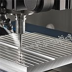
Here are two examples of high-speed machining, as done on Datron machines. A ¼” single flute cutter in 6061 aluminum, going 1/8” deep. The machining runs at 45,000 RPM and is cooled by Ethanol. The feed rate is 250”/min.
Secondly, using a 1/8” double flute high-speed cutter (HSC+) with low helical angle to machine through a 1/8” 6061 aluminum sheet. The machining runs at 50,000 RPM and is cooled by Ethanol. The feed rate is 200”/min.
There are certain rules of thumb for high-speed machining. First of all, avoid red-lining your spindle, as this increases wear and tear on it and significantly reduces its lifetime. Machine with maximum half the tooling diameter in Z. Machine with a smaller step-over but with higher feed rates. And finally, move fast and evacuate the heat with the chip.
Conclusion
It all comes down to the right tools for the right job. A golfer wouldn’t use a driver on the green, nor tee off with a putter. Conventional machines with low-speed, high-force spindles can’t meet the criteria for efficiently machining with small tools. Only a machine built from the ground up, for the sole purpose of high-speed machining with micro tooling, will deliver the efficiency and quality needed to manufacture most intricate, small parts.
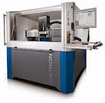
High-speed machining with micro tooling offers lower force, less tool breakage, no thermal growth, better surface finish, elimination of de-burring and de-greasing operations and less tool vibration. Spindle speeds between 25,000 and 60,000 RPM result in efficiency with small tools, better part quality and improved cycle times. Datron’s line of machines offer the features and advantages mentioned above and can help manufacturers to achieve efficiency and quality in small part production with micro tools. Datron offers machining systems with a typical working volume of 40” x 27” x 8”, and other sizes are available.
Micro tooling and high-speed machining defined
Micro tooling involves mills and drills with a diameter of 0.250” or less. It is required for very intricate or detailed machining and works best with high-speed spindles.
High-speed machining has no set definition or absolute parameters, but one workable definition is machining with spindle speeds of 25,000 RPM or more.
The challenges of machining with micro tooling
With a trend towards miniaturization in manufacturing, work piece sizes are decreasing and part versions are increasing. So, the use of micro tools is becoming more and more prevalent. However, efficient and cost-effective use of these small tools requires both the foresight to employ equipment specifically designed for them and a willingness to deviate from standard machining practices. This is primarily due to the fact that the spindles on conventional CNC equipment cannot achieve the higher RPM speeds required for small diameter tools. Even if they can, it puts undue stress on the equipment by constantly red-lining their spindles. As an example, a conventional CNC machining center running tools smaller than ½” in diameter at 10,000 RPM or less will result in unfavorable feed rates and costly tool breakage.
Often this tool breakage is blamed on operator error, incorrect machining parameters, or worse yet, simply the nature of small tools. The reality is that it’s due to the force of a conventional machine’s heavy spindle and its inability to reach the high RPM speeds required to effectively evacuate chips from the cutting channel.
Available technology
The best approach to efficiently machine with small tooling is a three-fold process. The three interrelated elements are: 1) high-speed machining technology, 2) optimized micro-tool design, 3) low-viscosity coolant.
High-Speed Machining Technology. The smaller the tools, the higher the spindle speed you will need to efficiently machine quality parts and avoid tool breakage. High-frequency spindles with speed ranges up to 60,000 RPM are ideal for milling, drilling, thread milling and engraving using micro tools.
High-speed machining technology uses high RPM rates, taking a smaller stepover, but with significantly increased feed rates. Move your hand through the flame of a burning candle. If you move too slowly, there’s enough time for the flame to cause damage. But if you sweep your hand swiftly through the flame, there’s insufficient time for the fire to damage your skin. The same principle applies to high-speed machining with micro-tooling. Move fast, and there’s insufficient time for heat to feed back into the part and cause issues.
During the machining process, the tool continually carves a chip out of the work piece. The generated heat develops approximately 40% from friction on each side of the tool, and 20% from the deformation (bending) of the chip. Therefore, about 60% of the heat is inside of the chip. Highspeed machining tries to evacuate the bulk of the heat with the chip, providing for a cleaner cut. The better machining quality is based on cooler tooling, lower machining forces, and therefore less vibration.
The high spindle speed reduces the chip load to less than 0.005”. Such a low chip load significantly reduces the forces between the tool and the material. High-speed/low-force machining yields less heat, reduces tool deflection, and allows machining of thinner walled work pieces. This all results in cooler machining, superior surface and edge quality, better accuracy and, as a by-product (of low force), easier workholding — since modular vacuum tables can be employed for quick set up and job changeover (particularly with thin flat substrates).
Optimized Micro-Tool Design. Scaling down the tool geometry of larger diameter tools to a smaller format yields unacceptable feed rates and unsatisfactory finishes. Tooling requirements change when tool diameter is decreased and spindle speed is increased. Conventional tooling using inserts is not appropriate for micro-tooling applications. This is primarily due to the high RPM rates rather than the tool diameter. Increased RPM rates require properly balanced tools with significantly increased chip room to assure proper chip removal and to prevent chip burn up. Efficient machining with small tools requires the tools to be optimized specifically for high-speed machining applications. The proper geometry of micro-tooling, together with high-speed spindles and the ideal coolant, can totally eliminate de-burring and de-greasing as secondary operations.
Low-Viscosity Coolant. While high-speed machining inherently reduces heat, the task of cooling a rapidly moving micro tool often requires coolant. Those dedicated solely to high-speed machining with small tools understand that coolant used with conventional CNC equipment is not optimal — and this is a perfect example of where thinking “out-of-the-box” is necessary when undertaking applications that require high-speed machining .
A small tool with intricate geometry turning at an extremely high RPM calls for a cooling and lubricating agent with a lower viscosity than water. Lower viscosity is needed because the coolant needs to make it to the cutting edge of the tool despite the high spindle speeds involved. Emulsion-based coolants have a higher viscosity than water, and thus are ineffective as a lubricant for high-speed machining with micro tooling.
But some micro-volume coolant spray systems can use ethanol, a form of alcohol which occurs naturally in the sugar fermentation process and exhibits a lower-than-water viscosity. The low evaporation point of ethanol makes it an extremely efficient cooling and lubricating agent for high-speed machining operations. Plus, while conventional flood coolant is petroleum based and needs to be properly disposed of, ethanol simply evaporates. This eliminates the costs associated with disposal. In addition, ethanol as a coolant does not leave any residue on the machined parts, thus eliminating the costly secondary operation of de-greasing parts.
Note: Ethanol coolant should only be used for machining of non-ferrous materials and not for machining steel-based materials.
Machine Dynamics
Using small micro tools just isn’t as easy as finding an adapter to hold a tiny tool in a 40 Taper spindle on a conventional CNC machine. Because that spindle was designed for large tools like a 3 inch fly cutter intended to “hog” out deep cuts in dense substrates. As such, it has so much torque and force that it just breaks small tools which is both inefficient an very costly over the long haul. The only option an operator has in this situation is to slow the RPM and feed rates down to a crawl — and this isn’t efficient either because it results in unacceptable cycle times.
A vivid, and perhaps comical, analogy is the Hemi-powered pick up truck vs. the sports car. The reality is that you wouldn’t compare the two or even consider racing them against on another. Why? Because the truck was designed with the power and force to haul or tow enormous mass, while the sports car was designed for speed and maneuverability. In essence conventional CNC manufacturers who tout the ability to run micro tools are like an auto manufacturer putting a spoiler and racing stripes on a clunky SUV and claiming that it now possesses the same qualities as a Porche. Well, just like you can’t put a spoiler and racing stripes on an SUV and expect it to perform like a sports car, you can’t retrofit a high-speed spindle onto a clunky conventional machine and expect it to efficiently accomplish high-speed machining with micro tooling.
When designing a machine, you can go in one of two directions. You can build your machine with a big motor and heavy mass to provide the force and torque to drive large tools. Or you can build a lighter machine with a high-speed, low-force spindle specifically designed for micro-tooling. Certainly both types of machines can be multi-purpose and perform a variety of functions — like milling, drilling, taping and routing. But that’s where multi-function ends. In the end, if efficiency and quality are important to you and you need to produce both large and small parts, you’ll end up with both types of machines working side by side on the same shop floor. While this may seem like a duplication in terms of equipment expenditure, the costs are quickly recouped through the R.O.I. associated with efficiency and versatility. You’ll produce better parts, quicker, at a lower cost.
The Solution
In consideration of high-speed machining centers exclusively, the best means of tackling micro tooling applications is to employ equipment that exhibits the key attributes detailed above (high-speed machining technology, optimized micro-tool design and low-viscosity coolant) all working together synergistically. If applied together this three-fold process can provide you with breathtaking manufacturing speeds and improved product quality. But the benefits don’t stop there. In addition, this process can totally eliminate secondary operations like de-burring and de-greasing.
Examples
Here are two examples of high-speed machining, as done on Datron machines. A ¼” single flute cutter in 6061 aluminum, going 1/8” deep. The machining runs at 45,000 RPM and is cooled by Ethanol. The feed rate is 250”/min.
Secondly, using a 1/8” double flute high-speed cutter (HSC+) with low helical angle to machine through a 1/8” 6061 aluminum sheet. The machining runs at 50,000 RPM and is cooled by Ethanol. The feed rate is 200”/min.
There are certain rules of thumb for high-speed machining. First of all, avoid red-lining your spindle, as this increases wear and tear on it and significantly reduces its lifetime. Machine with maximum half the tooling diameter in Z. Machine with a smaller step-over but with higher feed rates. And finally, move fast and evacuate the heat with the chip.
Conclusion
It all comes down to the right tools for the right job. A golfer wouldn’t use a driver on the green, nor tee off with a putter. Conventional machines with low-speed, high-force spindles can’t meet the criteria for efficiently machining with small tools. Only a machine built from the ground up, for the sole purpose of high-speed machining with micro tooling, will deliver the efficiency and quality needed to manufacture most intricate, small parts.
High-speed machining with micro tooling offers lower force, less tool breakage, no thermal growth, better surface finish, elimination of de-burring and de-greasing operations and less tool vibration. Spindle speeds between 25,000 and 60,000 RPM result in efficiency with small tools, better part quality and improved cycle times. Datron’s line of machines offer the features and advantages mentioned above and can help manufacturers to achieve efficiency and quality in small part production with micro tools. Datron offers machining systems with a typical working volume of 40” x 27” x 8”, and other sizes are available.
Subscribe to:
Posts (Atom)